
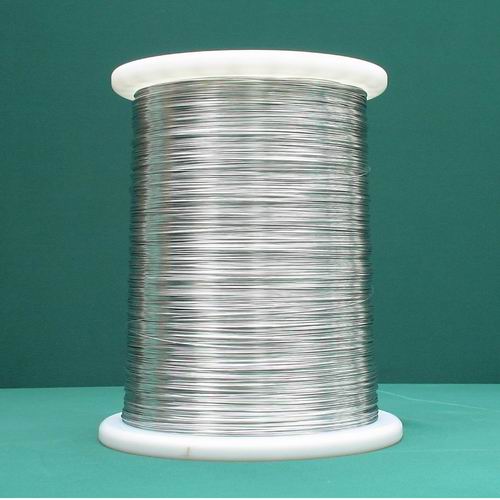
Tinned Plated Wire
Products
Tin-Plated Copper Wire
Lead-Free Tin-Plated Copper Wire
Lead-Free Tin-Plated wire complied with RoHS requirements is used to lead wire of different kinds of electronic parts, capacitors and resistors.
Features
1、Introduction
Our products include those characteristics as following:
· Homogeneous DIP bare copper wire, good tenacity and solder ability
· Solder surface is smooth and uniform, it is easy to weld and process
· Corrosion-proof, it can keep good solder ability and brightness when stored for long time · It is suitable for high speed and efficiency soldering equipment
· Our tin dipped copper wire is widely used in resistance, capacitor and other electric components.
We have the traditional soldering pot and the new instrument of solder ability testing of electronic components for surface mount technology by the wetting balance method to check the solder ability of tin plated wires. The new method was calculated the adhesion by the change of surface tension, buoyancy and wetting when the wire immersed into soldering pot. The operating diagram of the instrument is shown as following: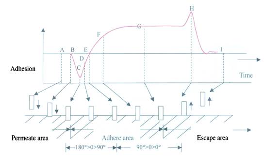
2、Solder Ability Test


Specifications
1、The designation and symbol of tinned copper wires:
| Designation | Softness | Symbol | Characteristics | |
|---|---|---|---|---|
Name | Content | |||
Lead free tinned copper wire | Tin 98% above | Hard wire | TCU-1 | Environmental protection required, easy to weld and good anti-oxidation ability |
Semi-hard wire | TCU-4 | |||
Soft wire | TCU-5 | |||
We can manufacture different tin/lead ratio and softness of tinned copper wire according to customer’s requirements. | ||||
2、The standard thickness of tin layer:
| Standard thickness(mm) | Symbol | Elongation (%) | Symbol |
|---|---|---|---|
1~3 | 3 | <5 | 1 |
3~5 | 7 | 20~25 | 4 |
>5 | 0 | >25 | 5 |
We can manufacture different thickness and elongation of tinned copper wire according to customer’s requirements.
3、Symbol of designation:
Example
4、The classifications and specifics of hard wires
| Size (mm) | Tolerance | Weight | Conductivity | Resistance | Tensile | Elongation |
|---|---|---|---|---|---|---|
0.20 | ± 0.008 | 0.2793 | 93.0 | 590.0 | 38.0 | -- |
0.23 | ± 0.008 | 0.3694 | 93.0 | 446.2 | 38.0 | -- |
0.26 | ± 0.010 | 0.4720 | 93.0 | 349.2 | 38.0 | -- |
0.29 | ± 0.010 | 0.5872 | 93.0 | 280.6 | 38.0 | -- |
0.32 | ± 0.010 | 0.7149 | 93.0 | 230.5 | 38.0 | -- |
0.35 | ± 0.010 | 0.8553 | 93.0 | 192.7 | 38.0 | -- |
0.40 | ± 0.010 | 1.1170 | 93.0 | 147.6 | 38.0 | 0.34 |
0.45 | ± 0.010 | 1.4140 | 93.0 | 116.6 | 38.0 | 0.35 |
0.50 | ± 0.010 | 1.7460 | 93.0 | 94.39 | 37.0 | 0.36 |
0.55 | ± 0.020 | 2.1120 | 94.0 | 77.19 | 37.0 | 0.37 |
0.60 | ± 0.020 | 2.5130 | 94.0 | 68.89 | 37.0 | 0.38 |
0.65 | ± 0.020 | 2.9500 | 94.0 | 55.28 | 37.0 | 0.40 |
0.70 | ± 0.020 | 3.4210 | 94.0 | 47.67 | 37.0 | 0.41 |
0.80 | ± 0.020 | 4.4690 | 94.0 | 36.49 | 37.0 | 0.43 |
0.90 | ± 0.020 | 5.6560 | 94.0 | 28.83 | 37.0 | 0.46 |
5、The classifications and specifics of soft wires
| Size (mm) | Tolerance | Weight | Conductivity | Resistance | Tensile | Elongation |
|---|---|---|---|---|---|---|
0.10 | ± 0.008 | 0.0698 | 93.0 | 2360 | -- | 10.0 |
0.12 | ± 0.008 | 0.1005 | 93.0 | 1639 | -- | 10.0 |
0.14 | ± 0.008 | 0.1368 | 93.0 | 1205 | -- | 10.0 |
0.16 | ± 0.008 | 0.1788 | 93.0 | 921.9 | -- | 10.0 |
0.18 | ± 0.008 | 0.2263 | 93.0 | 728.4 | -- | 10.0 |
0.20 | ± 0.008 | 0.2793 | 93.0 | 590.0 | -- | 10.0 |
0.23 | ± 0.008 | 0.3694 | 93.0 | 446.2 | -- | 10.0 |
0.26 | ± 0.010 | 0.4720 | 94.0 | 345.5 | -- | 10.0 |
0.29 | ± 0.010 | 0.5872 | 94.0 | 277.7 | -- | 10.0 |
0.32 | ± 0.010 | 0.7149 | 94.0 | 228.1 | -- | 15.0 |
0.35 | ± 0.010 | 0.8553 | 94.0 | 190.6 | -- | 15.0 |
0.40 | ± 0.010 | 1.1170 | 94.0 | 145.9 | -- | 15.0 |
0.45 | ± 0.010 | 1.4140 | 94.0 | 115.4 | -- | 15.0 |
0.50 | ± 0.010 | 1.7460 | 96.0 | 91.44 | 28.0 ¯ | 20.0 |
0.55 | ± 0.020 | 2.1120 | 96.0 | 75.59 | 28.0 ¯ | 20.0 |
0.60 | ± 0.020 | 2.5130 | 96.0 | 63.53 | 28.0 ¯ | 20.0 |
0.65 | ± 0.020 | 2.9500 | 96.0 | 54.13 | 28.0 ¯ | 20.0 |
0.70 | ± 0.020 | 3.4210 | 96.0 | 46.67 | 28.0 ¯ | 20.0 |
0.80 | ± 0.020 | 4.4690 | 96.0 | 35.73 | 28.0 ¯ | 20.0 |
0.90 | ± 0.020 | 5.6560 | 96.0 | 28.23 | 28.0 ¯ | 20.0 |
1.00 | ± 0.020 | 6.9820 | 96.0 | 22.87 | 28.0 ¯ | 20.0 |
1.20 | ± 0.020 | 10.050 | 96.0 | 15.88 | 28.0 ¯ | 20.0 |
6、The packaging type:
| Type | Symbol | Max. capacity |
|---|---|---|
Plastic bobbin | PT-1 | 3kg |
Plastic bobbin | P-3 | 5kg |
Plastic bobbin | P-5 | 8kg |
Plastic bobbin | PT-20 | 23kg |
Paper box | BX-20 | 25kg |
Plastic bucket | B-20 | 25kg |
7、Plastic bobbin size: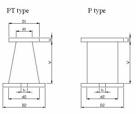
| Bobbin type | Flange dia. D(mm) | Barrel dia.d | Wide W | Thickness a | Hole dia.h | Bobbin weight | ||
|---|---|---|---|---|---|---|---|---|
D1 | D2 | d1 | d2 | |||||
PT-1 | 94.5 | 104 | 53 | 58.5 | 100 | 10 | 20 | 115 |
PT-20 | 210 | 230 | 130 | 150 | 245 | 15 | 30 | 900 |
P-3 | 128 | 75 | 105.5 | 7 | 20 | 185 | ||
P-5 | 160 | 70 | 92 | 11.5 | 20 | 220 | ||
| Package type | Dimension (mm) |
|---|---|
Paper box BX-20 | L´W´H=290´290´360 |
Plastic bucket B-20 | f´H=280´380 |


